The Residual Argument: Three Type 2 Surge Protectors and the Voltage That Slips Past
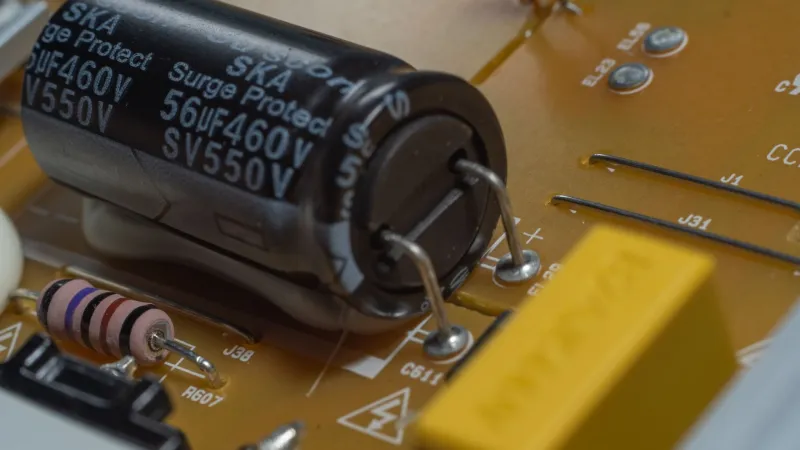
Surge protective devices have moved from the specialist panel to the everyday consumer unit. In a British home, a Type 2 module beside the main switch is now a familiar sight, often fitted during a consumer-unit change or added when a new appliance arrives. The commercial claim is simple: the device clamps the transient and the installation is protected. The engineering claim is narrower. A Type 2 SPD limits the voltage at its terminals under defined test conditions; what arrives at a socket, a router or a heat-pump controller depends on the whole path.
That distinction is not pedantic. It is the difference between a datasheet figure and an installation. To examine it, CavLab tested three Type 2 surge protective devices on the bench and then observed one of them in a domestic consumer unit, measuring the residual voltage at the device and at a downstream point. The aim was not to rank brands but to understand the gap between a declared voltage protection level and the transient that survives the copper.
What the datasheet actually specifies
A Type 2 SPD is selected under BS EN 61643-11 and installed according to BS 7671. The parameters that matter are the maximum continuous operating voltage, Uc; the nominal discharge current, In; the maximum discharge current, Imax; and the voltage protection level, Up. The last of these is the figure most often quoted and least often understood. Up is the residual voltage measured at the SPD terminals during a specified discharge-current test, usually an 8/20 µs waveform. It is not a guarantee for every current, every installation or every downstream load.
A device marked Up = 1.5 kV is not promising that 1.5 kV will appear at the fridge. It is stating a limit under a test arrangement that assumes short, direct connections and a defined current. Increase the current, lengthen the connecting leads, or change the impedance of the circuit, and the voltage across the protected equipment will rise. The datasheet is a starting point for selection, not a description of the installed system.
The bench arrangement
Three devices were chosen to represent the range found in UK distribution: a compact budget module, a mid-market unit with a status window, and a larger cartridge-based device from an established manufacturer. All were Type 2, all were intended for DIN-rail mounting, and all carried declared Up values between 1.2 kV and 1.5 kV. Each was tested with 8/20 µs current impulses at approximately 1 kA, 3 kA and 5 kA, using a surge generator and a current-viewing shunt. Voltage was recorded at the SPD terminals with a differential probe and at the far end of a 10 m length of 2.5 mm² twin-and-earth cable, terminated in a single socket.
The first result was unsurprising: clamping voltage rose with current. At 1 kA, all three devices held the terminal voltage below their declared Up. At 5 kA, the measured peaks were higher, though still within the datasheet limits for two of the three. The budget module behaved less predictably at the higher current, with a broader waveform and a higher peak than its declared figure suggested. That is not necessarily a failure; it is a reminder that Imax is a survival rating, not a clamping promise.
The second result was more useful. At the far end of the 10 m cable, the recorded peak was consistently higher than at the SPD terminals. The difference was not dramatic on the bench, but it was measurable: several hundred volts at the higher impulses. The cable was not adding energy; it was adding impedance and allowing the transient to develop differently along the run. In a real house, with longer cable, more junctions and different routing, that difference can grow.
The length of copper in the consumer unit
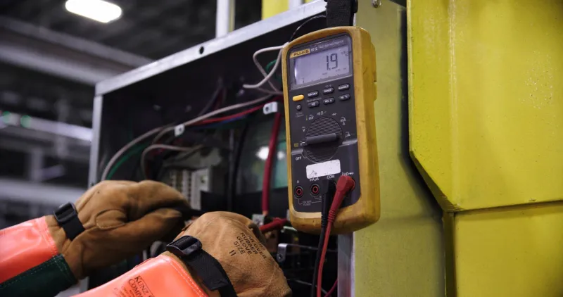
The field observation was made on a domestic consumer unit fitted with one of the three devices, connected with approximately 0.6 m of 6 mm² cable from the main switch to the SPD terminals. The SPD was correctly selected for the installation and had a status indicator showing end-of-life. A transient recorder was connected at a socket on the floor above, roughly 12 m of cable away.
Induced transients were injected into the supply with a coupling network, and the residual voltage at the socket was compared with the voltage at the SPD. The pattern from the bench repeated. The SPD clamped the transient at its own terminals, but the socket saw a higher peak. Part of this is simple inductance. A connecting lead of 0.6 m has an inductance of roughly 0.6 µH. At a rate of change of 5 kA over 8 µs, the inductive voltage across that lead alone can approach 400 V. Shorten the lead and the number falls; lengthen it and the number rises. The SPD cannot clamp a voltage that is generated after its own terminals.
This is why installation guidance is so insistent about short connecting leads and tight geometry. A neat consumer unit with the SPD adjacent to the main switch and the leads dressed close together is not merely good practice. It is part of the protective function. A device mounted at the far end of a DIN rail, connected with long loops of cable, may still operate, but it will let through more than the datasheet implies.
Where the claim meets the wall
The uncomfortable conclusion is that protected is not a binary state. A Type 2 SPD reduces the transient. It does not eliminate it, and it cannot compensate for an installation that gives the surge a long, inductive path to travel. The three devices in this sample all did something useful. None of them made the downstream voltage zero, and none of them could promise that every appliance would survive every event.
That matters in a British context because domestic electronics are diverse and often poorly characterised for surge withstand. A router, a heat-pump controller and a smart meter display do not share the same immunity. A residual peak that is harmless to one may be marginal for another. The SPD is one layer in a co-ordinated approach, not a substitute for unplugging sensitive equipment during a known storm or for maintaining good earthing and bonding.
Buyers should ask for more than a headline Imax. The useful questions are: what is Up at In, not merely the lowest declared figure; what backup protection does the manufacturer require; how will the device be connected; and how will its status be checked over time. A status window that is never inspected is a diagnostic that has been installed and forgotten.
The number after the word protected
The residual argument is not an attack on surge protection. It is an argument for treating the SPD as a system component rather than a talisman. The device clamps at its terminals; the installation decides what remains. In the consumer unit, the difference between a good and a mediocre installation may be a few hundred millimetres of copper and a few hundred volts of let-through.
That is the figure worth asking about. Not whether the unit is protected, but what voltage the protection leaves behind.